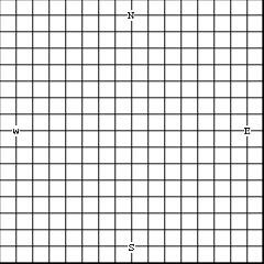
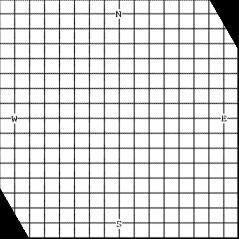
Suppose a camera on-board a satellite or a high-altitude aircraft is looking right down (at nadir view) and taking pictures of a flat
scene. Also suppose the camera is oriented such that the image columns represent lines of constant longitude and scanlines
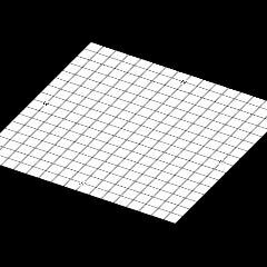
show lines of constant latitude. Therefore, the longitude-latitude lines will be as shown in Fig. 1a. Now, if the camera is rotated by
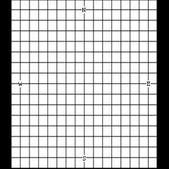
30 degrees about the y-axis when taking a picture, the longitude-latitude lines will appear as shown in Fig. 1b. Angle of rotation of
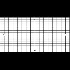
the camera about the y-axis is known as the roll. If the camera is rotated by 60 degrees about the x-axis, the longitude-latitude lines
appear as shown in Fig. 1c. The angle of rotation of the camera about the x-axis is known as the pitch. If the camera is rotated
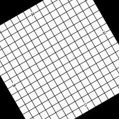
about its optical axis by 30 degrees, the longitude-latitude lines will appear as shown in Fig. 1d. Rotation of the camera about its
optical axis is know as the yaw. Yaw is also known as the heading. An image obtained with camera roll-pitch-yaw equal to
30-60-30 degrees is shown in Fig. 1e. Note that this is for the special case of a flat scene so that parallel lines in the scene appear
parallel in a captured image.
An image obtained by an off-nadir angle shows the longitude-latitude lines distorted. The lines no longer intersect at 90-degrees.
As a result, an image obtained by an off-nadir angle camera will not align with a map of the area by a rigid or similarity
transformation. To preserve the geometry of a captured image even when the camera is not viewing the scene at the nadir angle,
the image is transformed by a process known as ortho-rectification. Ortho-rectification, converts an image obtained at an arbitrary
roll-pitch-yaw of the camera to one as if obtained when roll, pitch, and yaw were 0. Ortho-rectifying the image of Fig. 1e using roll,
pitch, and yaw angles equal to -30, -60, and -30 degrees, respectively, the image shown in Fig. 1f is obtained. The only difference
between Figs. 1a and 1f is some intensity degradation due to image resampling. Otherwise, the geometry of the images is the
same. Ortho-rectification stabilizes the camera as if always looking down and heading toward the North. Ortho-rectified images are
easier to register and analyze because they are not geometrically distorted. Correcting for an image's geometry by
ortho-rectification, however, results in some intensity distortions in the image caused by the resampling process. Typically,
intensity distortions are very small compared to the geometry corrections gained; therefore, ortho-rectification generally improves
overall image quality. When the scene is not flat, orthorectification requires a DEM of the scene.
scene. Also suppose the camera is oriented such that the image columns represent lines of constant longitude and scanlines
show lines of constant latitude. Therefore, the longitude-latitude lines will be as shown in Fig. 1a. Now, if the camera is rotated by
30 degrees about the y-axis when taking a picture, the longitude-latitude lines will appear as shown in Fig. 1b. Angle of rotation of
the camera about the y-axis is known as the roll. If the camera is rotated by 60 degrees about the x-axis, the longitude-latitude lines
appear as shown in Fig. 1c. The angle of rotation of the camera about the x-axis is known as the pitch. If the camera is rotated
about its optical axis by 30 degrees, the longitude-latitude lines will appear as shown in Fig. 1d. Rotation of the camera about its
optical axis is know as the yaw. Yaw is also known as the heading. An image obtained with camera roll-pitch-yaw equal to
30-60-30 degrees is shown in Fig. 1e. Note that this is for the special case of a flat scene so that parallel lines in the scene appear
parallel in a captured image.
An image obtained by an off-nadir angle shows the longitude-latitude lines distorted. The lines no longer intersect at 90-degrees.
As a result, an image obtained by an off-nadir angle camera will not align with a map of the area by a rigid or similarity
transformation. To preserve the geometry of a captured image even when the camera is not viewing the scene at the nadir angle,
the image is transformed by a process known as ortho-rectification. Ortho-rectification, converts an image obtained at an arbitrary
roll-pitch-yaw of the camera to one as if obtained when roll, pitch, and yaw were 0. Ortho-rectifying the image of Fig. 1e using roll,
pitch, and yaw angles equal to -30, -60, and -30 degrees, respectively, the image shown in Fig. 1f is obtained. The only difference
between Figs. 1a and 1f is some intensity degradation due to image resampling. Otherwise, the geometry of the images is the
same. Ortho-rectification stabilizes the camera as if always looking down and heading toward the North. Ortho-rectified images are
easier to register and analyze because they are not geometrically distorted. Correcting for an image's geometry by
ortho-rectification, however, results in some intensity distortions in the image caused by the resampling process. Typically,
intensity distortions are very small compared to the geometry corrections gained; therefore, ortho-rectification generally improves
overall image quality. When the scene is not flat, orthorectification requires a DEM of the scene.
|
|
|
| Ortho-rectification (flat scene) |
| Image Registration and Fusion Systems |
| (a) (b) (c) |
| (d) (e) (f) |
Fig. 1. Images obtained at (a) roll=pitch=yaw=0 degrees; (b) roll=30 degrees,;(c) pitch=60 degrees; (d) yaw=30 degrees; (e) Roll=30
degrees, pitch=60 degrees, and yaw=30 degrees. (f) Ortho-rectification of image (e).
degrees, pitch=60 degrees, and yaw=30 degrees. (f) Ortho-rectification of image (e).
To obtain a license for this ortho-rectification software, follow this link =>
This software comes in a C/C++ static library compiled with
Microsoft Visual Studio under Windows PC. The library
comes with a C/C++ driver program demonstrating usage of
the software.
Microsoft Visual Studio under Windows PC. The library
comes with a C/C++ driver program demonstrating usage of
the software.
